 Here are the steps I took to make this tiny package useful for prototyping purposes. It’s by no means pretty but it will allow us to use the temperature switch on a breadboard.
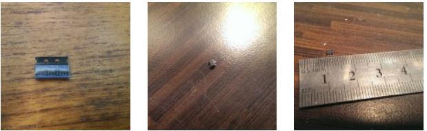
Now you can see why I laughed so hard.
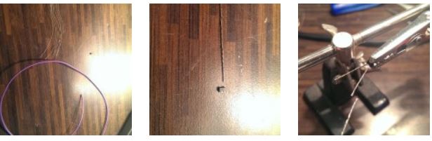
My first step was to find some wire thin enough so connect to the pins. I ended up stripping some already thin wire down (I don’t know the gauge of it but it’s a bit thinner than standard breadboard wire and multi-core). I then separated the cores but re-twisted 3 of the separate pieces together. On reflection, I didn’t need to mess around like this, I could have just used resistor legs.
Once the TMP708 was held in my handy hands, it was then a case of soldering a small amount of my new gauge wire to each of the legs. Again, this was a bad idea for reasons I’ll explain shortly.
Here are a few pics of the chips that arrived.
With that side of things out of the way, the next step was to build the board section.
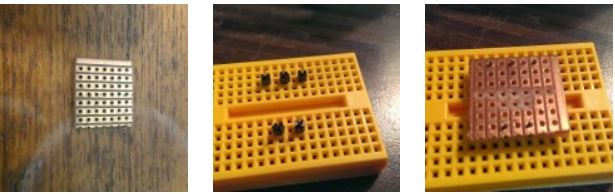
I used a spare piece of veroboard and some pin headers. I laid the pins out on a breadboard for several reasons, it helps arrange the pins before soldering, it keeps them straight while soldering and it also means that you don’t have to hold buy valium india anything other than your iron and solder.
One thing I had to do was remove all the copper beneath the area that the TMP708 would sit. I used a track cutter which is nothing more than a drill bit with a handle.
Once the pins were soldered into place, it was time to add the device itself.
Here are some pics of the board being made.
Now I’ll explain why soldering the legs to the chip first was a bad idea.
As I started soldering them to the pins, the heat travelled through the very thin wire and caused the solder on the legs of the device to melt and fall off.
Oh how I laughed……… not
Luckily, only two of the wires fell off so I soldered the three remaining ones and then made new wires for the other two. I soldered them to the board first and then to the TMP708. One thing I had to be careful of was that none of my wires shorted on the copper tracks of the veroboard.
Here are some images of the finished product. It’s very very ugly and will never make it into a finished device but for testing purposes it’s great. The next step is to draw a design out and etch some boards properly instead of using veroboard. We’ll update you with the results.