 Something we’ve been working towards is building a homebrew CPU from scratch in CPLD. If you’ve seen any of our “Getting Started with CPLDs” guide, you might have noticed that we’re working towards completing the ALU before we can start adding proper CPU features to it. This article is less about the CPLD side of things .
Building things on breadboards is fine but I often find that I either need to pinch something from the design, I knock wires out of place or there’s some other reason that it gets destroyed. In order to get round this, I’ve started building a modular control panel for my ongoing project. I’ve named it…. The Carlputer… ahem.
The first thing I decided I just HAD to have is nipple switches (toggle switches). I love the look of the old Altair 8800 and wanted to have something similar so off I went to Aliexpress and ordered 100 switches for £18. Bargain.
The next thing to do was build a panel for the switches to fit into. I was going to use some thin plywood or MDF at first but then realised that I have occasional access to a laser cutter. Off I went, design in hand and emerged with these lovely little panels. I’ve added LED holes above the switches because I thought it’d be nice to show the state of the switches. The other panel is for the output LEDs. I’ve made enough holes to expand up to 8bit but I’m only using 4bit for now.
Fitting the switches was a piece of cake. I’ve fitted the LEDs too but haven’t wired them up yet (apart from the grounds). All the switch and LED grounds are connected together. Also, the two switches on the far right are not connected buy xanax eu yet. These have been added to use later on as the project progresses. I’ve used CAT5 cable from each connection and soldered the ends to a piece of stripboard. I’ve then soldered pin headers onto the stripboard so I can jumper them to either the CPLD board or a breadboard for now. It’s ugly as hell but this is still in prototype stage so I’m ok with it for now.
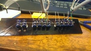
Populating the LED output board was much the same. I’ve used different coloured LEDs (because I ran out of red) and I’ve soldered resistors straight to the LEDs. Again, all the grounds are linked and it’s an ugly mess…. still not bothered…
Now I need something to hold these panels in place. Because I’ve designed the system to be modular, I wanted a way to be able to swap and change them as I see fit. The way round this was to use two pieces of wood with a recess cut into each piece for the panels to slide in to. Once they’re fitted into a small frame it’s done. I’ve added some pics of the build process.
All that’s left to do now is get it wired up to the CPLD. Another note to make is that in future I will probably not use CAT5 cable for the connection wires. It’s a little bit too brittle to use for something that gets moved around and messed with a lot. I keep having to re-solder broken connections. It’ll probably be fine to use the finished design but for prototyping it’s a bit kak.
I will update this project when it’s a bit further forward.
If you have any comments or questions, feel free to get in touch. We’d love to hear from you.